
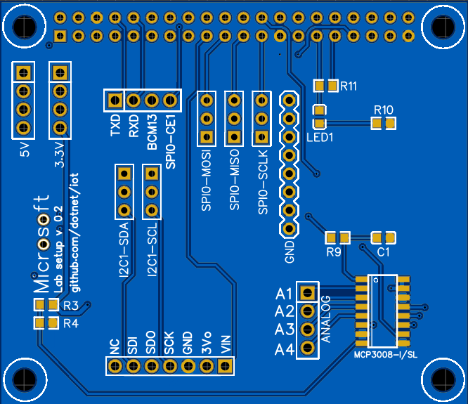
Raspberry Pi GPIO Test Expansion Bare PCB — .NET IoT
$2.00
$2.00 per bare PCB · 50 g · 2 layers. One unpopulated Raspberry Pi GPIO test expansion PCB based on the dotnet/iot design. For GPIO, SPI, I2C and PWM test setups using MCP3008 and a separate BME280 breakout module.
PCB only: Raspberry Pi, electronic components, headers and BME280 module are not included.
PCB production lead time: 2-3 days. PCBA production lead time: 5-10 days, subject to component availability and assembly-scope confirmation. Shipping transit time is additional.
Choose your PCB color: Green, Purple, Red, Yellow, Blue, White, Black or Matte Black.
For bare PCB orders, please enter your preferred soldermask color in the order notes at checkout. If ordering multiple products, specify the product name and color for each item. Example: Arisu PCB – Purple. Product images are references; the supplied PCB color follows your confirmed order requirements.
Prefer to order with your Gerber files? Upload your Gerber files on our PCB/PCBA online ordering page, select your PCB color and manufacturing specifications, and place your order directly. Pricing is calculated from your uploaded files and selected options.
5% of this product’s net sales goes to the shared DIYIPCB Open Hardware Fund, at no extra charge.
See the fund & rules →In stock
Description
PCBA production lead time: 5-10 days, subject to component availability and assembly-scope confirmation. Shipping transit time is additional.
Pricing and assembled PCBA enquiries
Bare PCB: US$2.00 per board, listed shipping weight 50 g. PCB production lead time: 2-3 days.
For assembled PCBA, please contact DIYIPCB or email service@diyipcb.com. Tell us your quantity and whether you require the BME280 module and optional headers. Assembly scope, price, weight and lead time are confirmed in the quotation. This checkout purchases the bare PCB only.
Raspberry Pi GPIO Test Expansion PCB
A two-layer bare PCB based on the System.Device.Gpio test board in the dotnet/iot project. The upstream documentation describes use with Raspberry Pi 3 for automated hardware-interface testing.
Functions and applications
- GPIO input/output test connections.
- SPI testing with an MCP3008 analog-to-digital converter.
- I2C testing with a separately fitted BME280 breakout module.
- PWM measurement through the test circuit and ADC.
- Embedded-software validation, IoT teaching and Raspberry Pi interface experiments.
Functions require assembly, compatible external hardware, software and Raspberry Pi interface configuration. Compatibility with other Raspberry Pi models should be checked against their pinout and software environment.
Main devices in the assembled design
- MCP3008-I/SL: SPI analog-to-digital converter.
- BME280 breakout module: temperature, humidity and pressure sensing via I2C; connects through a seven-pin header.
- Raspberry Pi: external host computer using the 40-pin GPIO connector.
What you receive
One unpopulated PCB. No MCP3008, BME280 module, Raspberry Pi, resistors, capacitors, LEDs, headers, cables or enclosure are included. The image is the upstream PCB design rendering for reference; it does not show an assembled product supplied by DIYIPCB.
Assembly planning
The upstream component list includes one MCP3008-I/SL, one BME280 breakout module, one 2×20 female header, one 1×7 female header, four 4.7k 0603 resistors and one 100nF 0603 capacitor. Additional male headers, an LED and a resistor are optional. Confirm exact parts, module pinout and optional assembly scope before ordering PCBA.
Source and production resources
- Original test-board documentation and component list
- Upstream Gerber and drill files
- Schematic PDF
- MIT license
Original project: .NET Foundation and Contributors. This independently manufactured DIYIPCB board is not an official Microsoft or Raspberry Pi product; no endorsement is implied.
5% of eligible net product sales supports the Open Hardware Fund at no extra charge.
MIT license — upstream copyright and permission notice
The MIT License (MIT)

Copyright (c) .NET Foundation and Contributors

All rights reserved.

Permission is hereby granted, free of charge, to any person obtaining a copy
of this software and associated documentation files (the "Software"), to deal
in the Software without restriction, including without limitation the rights
to use, copy, modify, merge, publish, distribute, sublicense, and/or sell
copies of the Software, and to permit persons to whom the Software is
furnished to do so, subject to the following conditions:

The above copyright notice and this permission notice shall be included in all
copies or substantial portions of the Software.

THE SOFTWARE IS PROVIDED "AS IS", WITHOUT WARRANTY OF ANY KIND, EXPRESS OR
IMPLIED, INCLUDING BUT NOT LIMITED TO THE WARRANTIES OF MERCHANTABILITY,
FITNESS FOR A PARTICULAR PURPOSE AND NONINFRINGEMENT. IN NO EVENT SHALL THE
AUTHORS OR COPYRIGHT HOLDERS BE LIABLE FOR ANY CLAIM, DAMAGES OR OTHER
LIABILITY, WHETHER IN AN ACTION OF CONTRACT, TORT OR OTHERWISE, ARISING FROM,
OUT OF OR IN CONNECTION WITH THE SOFTWARE OR THE USE OR OTHER DEALINGS IN THE
SOFTWARE.
Additional information
| Weight | 0.05 kg |
|---|---|
| PCB Layers | 2 |
| PCB Production Lead Time | 2-3 days |
| PCBA Production Lead Time | 5-10 days |
| PCB Color (Order Notes) | Green, Purple, Red, Yellow, Blue, White, Black, Matte Black |
Maker & product resources
Maker / seller: DIYIPCB · Source: .NET Foundation and Contributors
Hardware license: MIT
Source repository: https://github.com/dotnet/iot
Documentation: https://github.com/dotnet/iot/tree/main/src/System.Device.Gpio.Tests
Check the product description for specifications, included items, stock and fulfillment details.
Related products
-
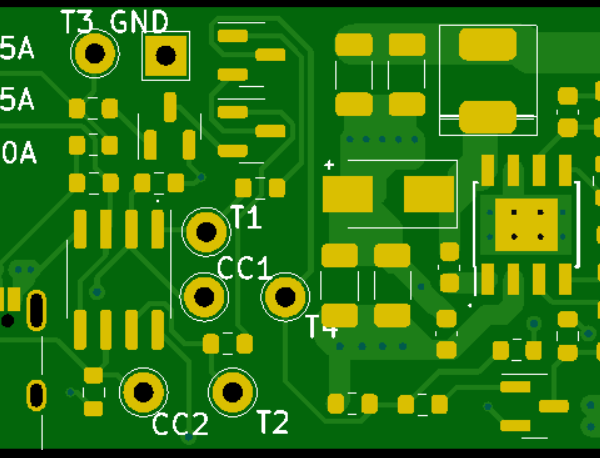
USB-C 3.3V Step-Down Converter — PCB / PCBA
Price range: $1.00 through $3.20Select options This product has multiple variants. The options may be chosen on the product page -
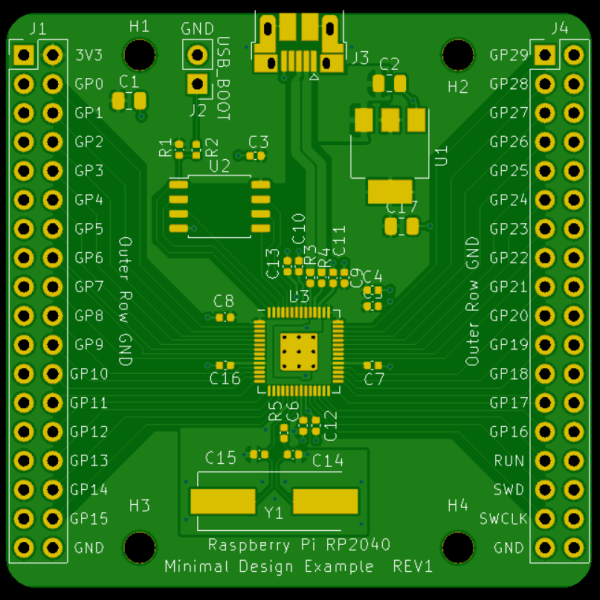
RP2040 Minimal Design — PCB / PCBA
Price range: $2.00 through $5.90Select options This product has multiple variants. The options may be chosen on the product page -
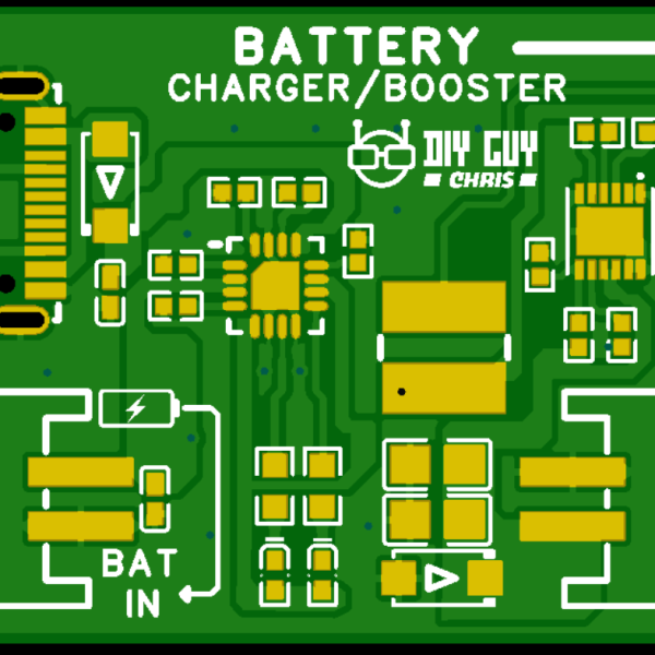
LiPo Charger & 5V Booster — PCB / PCBA
Price range: $2.00 through $4.50Select options This product has multiple variants. The options may be chosen on the product page -
Reviews
There are no reviews yet.